 MICE-Note 2002-xx October
2002
MICE-Note 2002-xx October
2002
TPG TRACKING FOR MICE
Bari, Legnaro, Geneva, Napoli, Zurich, …

MICE-Note 2002-xx
October 2002
The MICE TPG project
Bari, Legnaro, Frascati, Geneva, Napoli, Zurich
General
principle
Ttype of data
provided, resolution, operation mode and mechanical description
Ssensitivity to
background
Ttesting
programme
Ccost and time
scale
CONTACT &Testing program Emilio Radicioni
Test chamber: Giulio Saracino
Concept: Ugo Gastaldi
Electronics: Luca
Malgeri
TPG
simulation: Vladimir Grichine
Reconstruction: Gabriella
Catanesi, Mario
Campanelli
MICE detector taskforce conveners
Alan Bross, Vittorio Palladino
MICE Spokesmouse Alain Blondel
A time
projection chamber with GEM readout (TPG) is being developed as an alternative
to scintillating fibers. This type of device can produce a large number of
points on each track and a minimal amount of material, at the
expense of a longer integration time. It is also
inexpensive.
The reasons for a TPC with GEM amplification as a tracking device for MICE can be summarized in a few
points:
·
A TPC presents a light and uniform material along and across the beam phase-spaceline, yet producing a large number of points on each track.
·
The GEMs, manufactured by standard photolithographic
processes, are
less expensive than the traditional electron multiplication for TPCs (usually
wire chambers); at
the same time, the
GEMs are able to minimize the ion feedback into the drift volume, so reducing
the risk of uncontrolled field distortions.
·
By choosing an appropriate gas mixture, it is
possible to make the detector transparent to the X-ray background emerging from
the RF cavity. This allows to counterweight the disadvantage of the long
integration time.
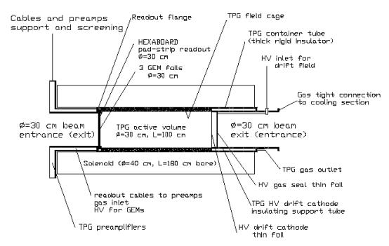
A sketch of the envisaged device is shown in figure
1 for the downstream spectrometer. An
identical one will be installed in the upstream spectrometer. The operational principles of the device are
as follows. The sensitive volume of 1m long and 30 centimeters diameter is situated in the homogeneous magnetic
field region of the spectrometer solenoids. The electric field provided by a
field cage surrounding the sensitive volume is parallel to the guiding magnetic
field. The charges produced by ionization of muons are collected on the far
side of the chamber with respect to the cooling section, so as to ensure a
minimum of material. The charges are amplified by GEM foils, and read-out on a
plane of pads from which the signal is shaped in preamplifiers and digitized by flash-ADCsfast ADCs. The total length of the chamber
corresponds to about
120 100 samplings at a drift velocity of 1.7
cm/ms, so that the device provides for each track
120 100
2D points times three coordinates. The chamber will be filled with low mass gas
(a Helium dominated mixture) thus reducing multiple scattering and offering
very small conversion probability for X-rays resulting from the cavities dark
current.
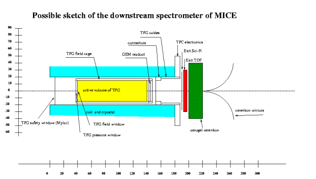
Fig.
1 View of the downstream spectrometer of MICE with a TPG as tracking
device.
32. Characteristics and performance of
the chamber
A
complete definition of the operational parameters of the chamber will only be
possible after a full scale test to be performed in spring-summer 2003 using
the HARP TPC magnet, field cage, digitizing electronics and gas system at CERN.
The proponents of the project have been previously involved in the conception, construction and
operation of the HARP TPC, and can provide a large fraction of the electronics.
Operation
of drift chambers with a helium-based mixture is quite customary, and
performance figures will be given here for a 90%He, 10% iso-butane mix at
atmospheric pressure. A drift voltage
of 500 V/cm provides a drift velocity of about 1.72cm/ms.
The maximal potential of -50 kV is situated in the plane of the field window
and needs to be degraded in less than 5cm of insulator in the outward direction
of the solenoid,, (this
can be done with solid insulator such as Teflon,) and in less than about 50 cm in the
direction of the liquid hydrogen absorbers , (this can be done with a suitable gas, e.g. low
pressure N2,
or with vacuum).
The
most probable number of primary ionization electrons along a minimum ionizing
muon is calculated to be 12 per cm. These electrons will drift toward the GEMs
with a transverse diffusion of 1.4 mm.Öz[m],
and a similar longitudinal diffusion. The
GEMs are made of 50- micron
thick foils with holes of 70 microns diameter at a pitch of 150 microns, as shown in Fig.2. . They
introduce very littlea small additional diffusion;, on the primary electrons (this is not fully true: oneeach primary electron will produce a “spray” of about 0.5 mm to 1mm transverse in diameter on the readout plane. This parameter is not well known and will be
measured in the forthcoming tests. This is
anyway good, since it gives a sort of “pad response function”). The
read-out board described below has a pitch of 450 microns, contributing also
very little to the resolution. If the exposure time of MICE during the RF pulse
is of the order of 500 microseconds, the available ADCs allow digitization in
1024 time slots of 500 ns second each. Each track is then sampled in 120100 time slots
of 500 ns, 0.851cm
long, containing 102
primary electrons each, giving 120100 points with
a spatial resolution,
in the worst case, of the order of the pitch
of the readout plane500 .Öz[m] microns each. In a perfect chamber this would give a
transverse momentum resolution of about 50 KeV/c. ? 0.2 MeV/c ?.(to be verified,
action Mario)
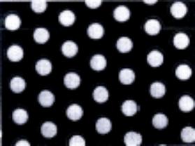
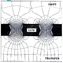
Fig.
2 Photograph of the GEM showing the 70 microns diameter holes at a pitch of 150
microns, and description of the electric field lines in the Gas Electron
Multiplier (GEM) foils.
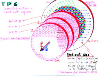
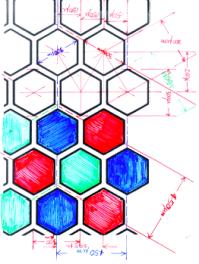
Fig 3: The TPG read-out: left: the 3 GEM foils
providing amplification to the hexaboard. Right: the hexaboard structure with a
third of the pads (blue) connected in strips at 30o, one third at
120o (red), and one third at 90o (green).
The amplification in each GEM
will depend on the high voltage, but it is planed to work at an amplification
level of 20-50 per GEM, giving a total signal of 104 to 105
electrons on the pad plane per primary electron. These will be read-out by a
hexaboard as described in Fig.3. The signal is distributed among several
individual hexagons. The hexagons could in principle be readout individually,
but for cost reasons the hexagons will be connected to form strips in three
orientations Each primary electron will
thus give signals in at least three projections. The strip signals, will be
collected from the pad plane and send over flat cables of 16 channels each to
the preamp boards. In the present
design, each preamp board will collect 48 channels. The signal will be shaped
to a length commensurate to the sampling frequency of 500 ns, and then sent to
the FADCs. The FADCs from the HARP TPC will be used. .
Prototype preamp boards in “HARP”
style and adapted to MICE geometry have been produced and delivered. The
channel count is 667 per coordinate, a total of 4000 for two TPGs.
Fig
4. Description of the elements of the TPG.
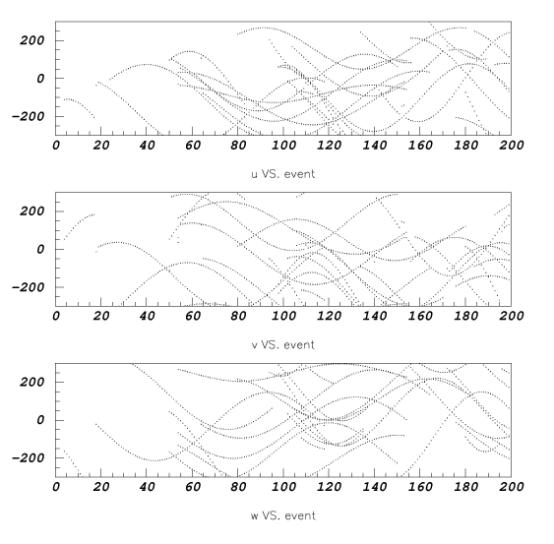
Fig 5. Simulation of 100
microseconds of data taking with the upstream MICE TPG. Vertical axis is the strip number in each of the three projections
(u,v,w at 30, 90 and 150 degrees). Horizontal axis is the time slot number. Each
time slot is 500 ns. The muon rate is assumed to be 0.1 per ISIS proton bunch,
i.e. 3 per microsecond.
Two kinds of backgrounds can be
detrimental on the performances of the TPG.
The first kind is the pollution by RF noise, both
in the experimental area and in the beam pipe.
Thanks to the mechanical construction, most parts
of the detector are screened by thick aluminum parts, which will be duly
grounded. The only parts that cannot be enclosed in
massive metallic pieces are the GEMs: RF noise coming from the cavity may, in principle, reach the readout plane and
produce fake hits. However,
even if the GEMs
are very light, the
thin Cu layer deposited on them is already an effective screen for 200MHz EM waves, since its thickness is equivalent to the skin
depth.
Even if we are confident in
the immunity of the detector to RF noise, specific tests will be performed with
a small prototype chamber to make sure that all the details of the RF immunity, from the readout plane to
the FADCs, will
be understood.
The second kind of noise
will come from the X-ray emission from the cavity. Conversion of X-rays may
produce fake hits and, ultimately, endanger the ability to reconstruct a clean
set of tracks.
As we have seen, one
time-slice corresponds – with the present indication of gas mixture and field cage potential – to about 0.85cm. In terms
of conversion probability in the gas, this amounts to about 10-4 for X-ray energy of 10KeV.
If one makes the hypothesis
of a primary X-ray rate of 1GHz 10KeV photons over the whole diameter of the detector, each
0.85cm slice will integrate a few conversions. This is perfectly tolerable, since each slice is
read out in 1800 coordinates. Softer X-ray spectra may of course be more
dangerous, but we
estimate that the rate may still be tolerable at 5KeV.
More precise understanding
of the influence of the X-ray background will be possible when an X-ray
emission spectrum will be measured.
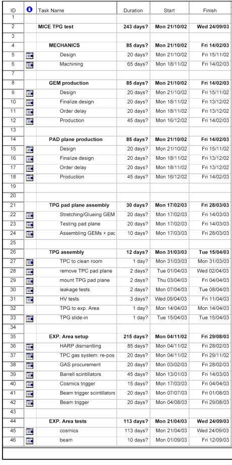
5. Preliminary timescale for tests in 2003
The tests of a TPC with GEMs read-out will be
carried with several aims:
First, the capacity to shield the detector against
RF electromagnetic radiation will be tested on a small chamber built in
Frascati, equipped with electronics similar to that which will be used for the
final detector. This will be done at CERN with the help of the RF group who
will provide a tunable antenna radiating at 200 MHz.
Then the exact performance of the read-out system,
diffusion properties in the gas and especially in the GEMs will be tested in a
0.7 T magnet with the HARP solenoid and field cage. This will be a test of a
full size readout board, in which an already sizeable amount of electronic
channels will be involved (600). If the test is successful the readout board
could be part of one the final MICE trackers. Fig 6 shows the layout of the test in the HARP
solenoid.
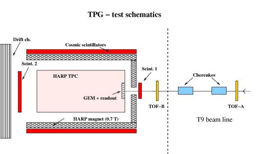
Fig
6. Schematic of the test of the TPG read-out in the HARP TPG.
At the same time the response of the TPG and in
particular of the GEMs to RF field emission should be tested. The effect of photon conversions in the TPG
gas is easily calculable, their effect on the GEMs themselves is not. The 88
MHz test cavity at CERN will be powered at the beginning of 2003.
Alternatively, one could bring a small chamber to the labG at Fermilab. This
may be a critical issue and should proceed quickly.
The exact schedule for
construction of the final detectors is being worked out.
From preliminary estimates
based on the construction for the tests in 2003, one can estimate the cost of
the readout and amplification system to be less that 100K$ per tracking
station.
Based on the cost of the
HARP field cage, whose design is, for the moment, being considered for the MICE
TPGs, we estimate building the two field cages may account for 200K$.
Ancillaries like the gas and
HV system may account for another 100K$.
The Cern Gas Detector Development page:
The
MICE web page:
http://hep04.phys.iit.edu/cooldemo/
The CERN muon storage rings web page
http://muonstoragerings.web.cern.ch/muonstoragerings/
The
MICE LOI submitted to PSI and RAL can be found here:
http://proj-bdl-nice.web.cern.ch/proj-bdl-nice/cool/loi-final-ral.pdf
One
can see there that the tracking devices that were considered in November 2001
were either scintillating fiber trackers or silicon trackers. A sketch of MICE
with these trackers is here:
http://proj-bdl-nice.web.cern.ch/proj-bdl-nice/cool/micesketchold.pdf
One of the problems of these proposals was the
expected noise from photons and electrons generated by the RF cavities of the
cooling section. In particular, the combination of inefficiencies in the
scintillating fibers and noise made it feared that reconstruction would be
seriously hampered by ambiguities. G. Barr discussed this in this note:
http://proj-bdl-nice.web.cern.ch/proj-bdl-nice/cool/barrnoisenote.pdf
In February 2002 Ugo Gastaldi suggested that one
could use a TPC with GEM readout for the trackers of MICE. The first ideas and
sketches together with a possible scheme for the readout can be found in this
talk:
http://hep04.phys.iit.edu/cooldemo/detectors/gastaldi_32002.pdf
http://proj-bdl-nice.web.cern.ch/proj-bdl-nice/cool/gastalditpgdraft.pdf
which
was presented in one of the MICE detector working groups meetings
http://hep04.phys.iit.edu/cooldemo/detectors/detectors.html
in March 2002
The readout has been discussed by
Emilio Radiccioni
http://proj-bdl-nice.web.cern.ch/proj-bdl-nice/cool/tpgemiliomarch2002.pdf
who also presented a program of tests:
http://hep04.phys.iit.edu/cooldemo/cm/cm4/talks/radicioni_tpg.pdf
The track reconstruction and resolution was studied by Mario Campanelli
http://hep04.phys.iit.edu/cooldemo/cm/cm4/talks/campanelli_tpg.ps
This note describes the proposal of a Time Projection
chamber for MICE with GEM read out. It is understood as a beginner’s
introduction with the sake of providing refernces for those interested in the
project.
The MICE LOI submitted to PSI and RAL can be found here:
http://proj-bdl-nice.web.cern.ch/proj-bdl-nice/cool/loi-final-ral.pdf
One can see there that the tracking devices that were considered in November 2001 were
either scintillating fiber trackers or silicon trackers. A sketch of MICE with
these trackers is here: http://proj-bdl-nice.web.cern.ch/proj-bdl-nice/cool/micesketchold.pdf
One of the problems of these proposals was the expected
noise from photons and electrons generated by the RF cavities of the cooling
section. In particular, the combination of inefficiencies in the scintillating
fibers and noise made it
feared that reconstruction would be seriously hampered by ambiguities. G. Barr
discussed this in this note:
http://proj-bdl-nice.web.cern.ch/proj-bdl-nice/cool/barrnoisenote.pdf
In February 2002 Ugo Gastaldi suggested that one could
use a TPC with GEM readout for the trackers of MICE. The first ideas and
sketches together with a possible scheme for the readout can be found in this talk:
http://proj-bdl-nice.web.cern.ch/proj-bdl-nice/talks/ugo.pdf
which was presented in one of the MICE detector working
groups meetings
http://hep04.phys.iit.edu/cooldemo/detectors/detectors.html
in March, see
http://hep04.phys.iit.edu/cooldemo/detectors/detectormeetingMar2002.html
This having a rather imprecise timing information (100
ns time slots at least) it would have to be complemented with at least one
plane of scintillating fibers and a segmented time-of-flight system.
Nevertheless, the fact
that it could provide hundreds of space points along a track with potentially
very small multiple scattering (for a He-isobutene filled TPG) allied with very
small mass for photon conversions, make it a very interesting option. The space
resolution with Helium
filling needs to be evaluated.
The readout has been discussed by Emilio Radiccioni and
seems to be quite OK:
http://proj-bdl-nice.web.cern.ch/proj-bdl-nice/cool/tpgemiliomarch2002.pdf
Finally the issue of pulling out the signals will have
to be investigated in detail, for reasons of noise and of the relationships
with the other detectors. A possible sketch of how to do this for the
downstream spectrometer
can be found here.
http://proj-bdl-nice.web.cern.ch/proj-bdl-nice/cool/micesketch.pdf
What needs to be done?
Ahe first and most urgent thing to do in my opinion is
to begin the hardware test
of the readout cleanliness in the vicinity of a mega-monster: the RF cavities
are a mere three meters away in the MICE set up and at the time when the muons
pass by there are being powered by an instantaneous power of 4 MW! this is bound to require very careful
shielding of the readout system, if it can work at all.
Also needed is a simulation of the performance of this
device plugging in first the space resolution as function of drift time, then
the possible effect of noise.